

- Almost same narrow band and SWR plots
- Almost same far fields plots
- Aprox 5.7 db more gain in favour of Moebius style for 10 degrees elevation
- Aprox 3.4 db more gain in favour of Moebius style for 45 degrees elevation

The lack of space as well as the radio noise specific to the urban area where I live creates me problems for the traffic on lowbands. Being a fan of the 40 meter band, I tried to make a Moebius antenna to use only at the reception. After the first model made and tested, I realized that I need to understand a little more about how this antenna should be seen.
What is a Moebius Antenna? Apparently it is a multi-spiral magnetic antenna, at least that’s how most authors present it. Although I found many references, I was unable to identify an author who would indicate a calculation formula that would allow a design to start from the basic parameters.
Let see how is looking a Moebius loop. I am using a diagram from Ofer Aluf and his calculations (https://www.researchgate.net/publication/322351098_Moebius_loop_antenna_system_stability_analysis_under_parameters_variation).
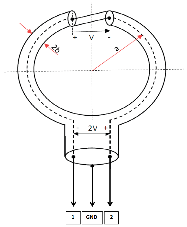
Unfortunately, the theoretical formulas presented by the author can be more difficult to apply in amateur mode, although the study mentioned above is closest to the proposed purpose.
Because I followed a more empirical approach, I made the following sketch, which I then tried to turn into something that could be mathematically modeled with simpler tools.

RED = TURN no 1
BLUE = TURN no 2
BLACK = common point (coaxial screen)
What is the red circle ? Is an inductance with a distributed capacitance. The inductance has 2 components: the inductance of the coaxial cable and the inductance of the 1 turn coil formed by the coaxial piece. Same, the blue circle.So, we can translate our antenna into the following circuit: 2 parallel LC mutual coupled.

For the first Moebius loop builded I used H1000 coaxial cable with 80 pF/m capacitance and 2 microH/m.

The diameter of the loop is 150 cm, using the H1000 pieces of 240 cm each.
The total lenght of coaxial cable is 580 cm, a very important aspect to be used later regarding the capacity of loop.
C= 80 (pF/m) x 2,4 (m) x 2 = 192 x 2 = 384 pF
(capacity calculated from H1000 datasheet)
The measured inductance of the each coils was 5.3 microH.
(between Red and Black / Blue and Black)
The measured inductance of entire 2T coil (Red and Blue) was 21.11 microH.
21.11/4 = 5.27 microH (a small difference from 5.3 microH, acceptable)


Now, the big question. My intention was to use this antenna for 7 Mhz. Where is the resonant point ? With variable capacitor open (minimum capacity)…

F res = 3141 kHz….
Clearly, the antenna cannot be tuned in 40 or 80 meter bands.
1st Question – Why 3141 kHz ?
So, we have 2 parallel LC mutual coupled, first LC is red turn coil with distributed capacity of the coaxial, the second LC is the blue coil with the distributed capacity of the coaxial. But beware, its own capacity is that of the whole piece of coaxial cable, not just half of it.
So, for L= 5.30 microH and C=384 pF the theory say, Fres = 3527 kHz.
The error is somewhere to 11-12 %,quite a lot, but the approach can be useful in an empirical design.
The next step was to adjust the variable capacitor to tune the antenna to 1840 Khz. The green capacitor (from coaxial inner to blue was found to be 82 pF for optimum SWR).

And now, the results for 2 consecutive nights, listening FT8 mode on 160 m band (600 and 500 different stations heard).


Conclusions
Bibliography
Moebius loop antenna system stability analysis under parameters variation – Ofer Aluf
Software for magnetic loops (YO4UQ) - https://www.radioamator.ro/articole/files/920/SOFT_MagLOOP_2007.xlsx
To be continued with: